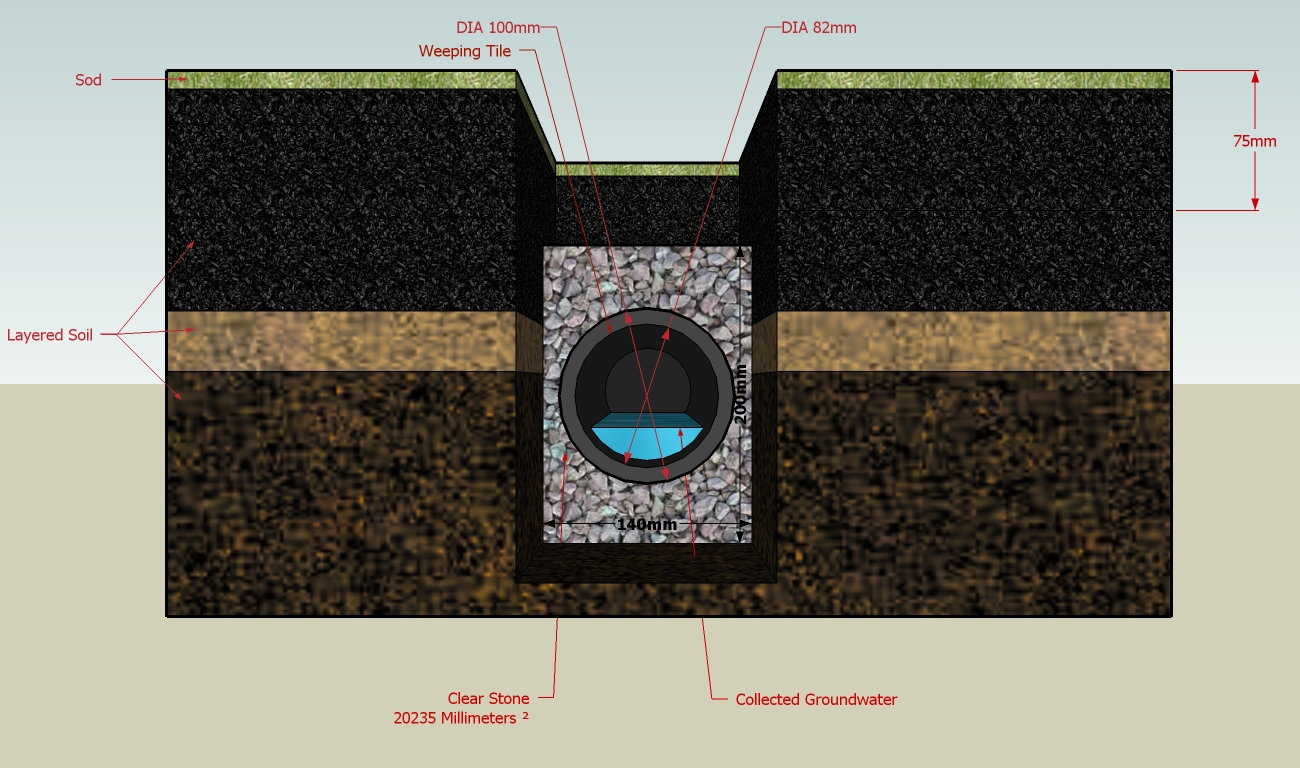
Subsurface Drain

Definition
A perforated conduit such as a pipe, tubing, or tile installed beneath the ground to intercept, collect, and convey excess ground water to a suitable stable outlet.
Where Practice Applies
- To provide a dewatering mechanism for draining excessively wet soils.
- To improve soil and water conditions for vegetative growth.
- To prevent sloughing of steep slopes due to ground water seepage.
- To improve stability of structures with shallow foundations by lowering the water table.
Advantages
- An effective way to lower the water table.
- Subsurface drains often provide the only practical method of stabilizing excessively wet, sloping soils.
Disadvantages/Problems
- Problems may be encountered with tree roots.
Planning Considerations
- Contact the local Conservation Commission regarding any work conducted in a wetland resource area. The Wetlands Protection Act requires that for work conducted in a wetland resource area, or within 100 feet of a wetland resource area, the proponent file a "Request for Determination of Applicability" or a "Notice of Intent" with the Conservation Commission.
- Subsurface drains usually consist of perforated, flexible conduit installed in a trench at a designed depth and grade. The trench around the conduit is often backfilled with a sand-gravel filter or gravel envelope. Backfill over the drain should be an open, granular soil of high permeability.
- Subsurface drainage systems are of two types; relief drains and interceptor drains. Relief drains are used either to lower the water table in order to improve the growth of vegetation, or to remove surface water. They are installed along a slope and drain in the direction of the slope. They can be installed in a gridiron pattern, a herringbone pattern, or a random pattern.
- Interceptor drains are used to remove water as it seeps down a slope to prevent the soil from becoming saturated and subject to slippage. They are installed across a slope and drain to the side of the slope. They usually consist of a single pipe or series of single pipes instead of a patterned layout.
Design Recommendations
- Subsurface drain should be sized for the required capacity. Design charts are available in Natural Resources Conservation Service references and from other sources. Manufacturers of special purpose drain configurations can provide instructions for design.
- The minimum velocity required to prevent silting is 1/4 feet per second. The line should be installed on a grade to achieve at least this velocity.
- The outlet of the subsurface drain should empty into a receiving channel, swale, or stable vegetated area adequately protected from erosion and undermining.
Construction Recommendations
- The trench should be constructed on continuous grade with no reverse grades or low spots.
- Soft or yielding soils under the drain should be stabilized with gravel or other suitable material.
- Deformed, warped, or otherwise unsuitable pipe should not be used.
- A sand-gravel filter at least three inches thick should be placed all around the pipe. Manufactured filters designed for the purpose, such as filter fabric, may be used as alternatives.
- The trench should be backfilled immediately after placement of the pipe. No sections of pipe should remain uncovered overnight or during a rainstorm. Backfill material should be placed in the trench in such a manner that the drain pipe is not displaced or damaged.
Maintenance
- Subsurface drains should be checked periodically to ensure that they are freeflowing and not clogged with sediment.
- The outlet should be kept clean and free of debris.
- Surface inlets should be kept open and free of sediment and other debris.
- Trees located too close to a subsurface drain often clog the system with their roots. If a drain becomes clogged, relocate the drain or remove the trees as a last resort. Drain placement should be planned to minimize this problem.
- Where drains are crossed by heavy vehicles, the line should be checked to ensure that it is not crushed.
References
Massachusetts Department of Environmental Protection, Office of Watershed Management, Nonpoint Source Program, Massachusetts Nonpoint Source Management Manual, Boston, Massachusetts, June, 1993
U.S. Environmental Protection Agency, Storm Water Management For Construction Activities EPA-832-R92-005, Washington, DC, September, 1992.
Washington State Department of Ecology, Stormwater Management Manual for the Puget Sound Basin, Olympia, WA, February, 1992.