Bioretention Areas & Rain Gardens
Description

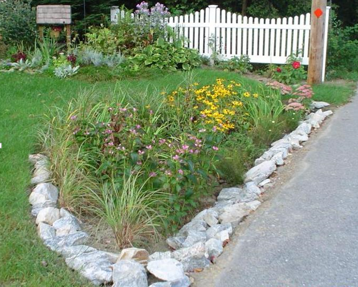
A rain garden is a bowl-shaped garden designed to capture and absorb stormwater.
Bioretention areas (also referred to as bioretention cells or rain gardens) use soil, plants and microbes to treat stormwater before it is infiltrated or discharged. Bioretention areas are shallow depressions filled with sandy soil, topped with a thick layer of mulch, and planted with dense vegetation.
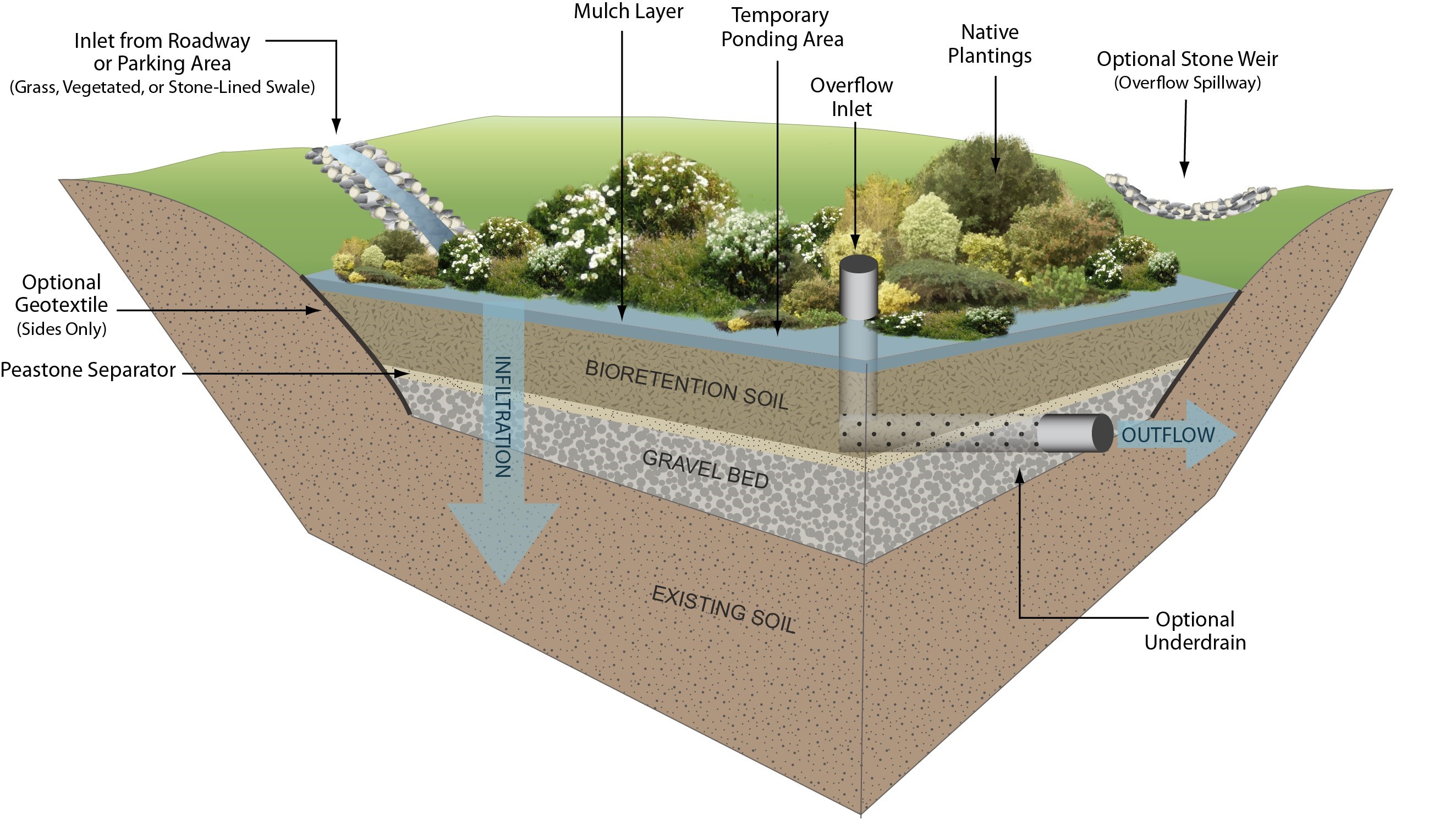
Stormwater runoff flows into the bioretention area, percolates through the soil (which acts as a filter) and eventually drains into the groundwater; some of the water is also absorbed by the plants. Bioretention areas are usually designed to allow ponded water and with an overflow outlet to prevent flooding during larger storm events. Where soils have low permeability or where faster drainage is desired, designers may incorporate a perforated underdrain that routes to a storm drain system.
Bioretention areas can provide excellent pollutant removal and recharge for the "first flush" of stormwater runoff. Properly designed bioretention areas will remove suspended solids, metals, and nutrients. Distributed around a property, bioretention areas can enhance site aesthetics. In residential developments they are often marketed as property amenities. Routine maintenance is simple and can be handled by homeowners or conventional landscaping companies, with proper direction.

Bioretention areas are similar to rain gardens, but are more highly engineered to include an underdrain, overflow inlet, gravel bed, and engineered soils to promote infiltration.
Ability to Meet Massachusetts Stormwater Management Standards
| Standard | Description |
| 2 Peak Flow | N/A |
| 3 Recharge | An exfiltrating bioretention area provides groundwater recharge. |
| 4 TSS Removal | 90% TSS removal credit with adequate pretreatment |
| 5 Higher Pollutant Loading | Can be used for certain land uses with higher potential pollutant loads if lined and sealed until adequate pretreatment is provided. Adequate pretreatment must include 44% TSS removal prior to infiltration. For land uses that have the potential to generate runoff with high concentrations of oil and grease such as high intensity use parking lots and gas stations, adequate pretreatment may also include an oil grit separator, sand filter or equivalent. In lieu of an oil grit separator or sand filter, a filtering bioretention area also may be used as a pretreatment device for infiltration practices exfiltrating runoff from land uses with a potential to generate runoff with high concentrations of oil and grease. |
| 6 Discharges near or to Critical Areas | Good option for discharges near cold-water fisheries. Should not be used near bathing beaches and shellfish growing areas. |
| 7 Redevelopment | Suitable with appropriate pretreatment |
Applications and Design Principles
Bioretention areas are suitable in a wide range of climatic and geologic situations. Common applications for bioretention areas include parking lot islands, median strips, and traffic islands. Bioretention is often a feasible "retrofit" that can be accomplished by replacing existing parking lot islands or by re-configuring a parking lot during resurfacing. On residential sites bioretention areas are commonly used for rooftop and driveway runoff.
Bioretention areas are usually sized (based on soil media void space and ponding area) to capture and treat the water quality volume (usually between 0.5 – 1.0 inches of runoff, depending on local requirements).
Bioretention Areas are typically designed in layers as follows (from bottom of excavation to surface):
- Impermeable liner (optional)
- Gravel layer (approximately 12 inches) with optional underdrain
- Pea stone layer (approximately 4 inches)
- Bioretention soil media composed of 40% sand, 20-30% topsoil, 30-40% compost (between 24-48 inches)
- Fine-shredded hardwood mulch (approximately 3 inches)
- Ponding depth (varies with site conditions; usually between 6-9 inches)
- The planting plan typically includes herbaceous perennials and shrubs which can tolerant frequent ponding, saline conditions, and extended dry periods.
In very permeable soils, bioretention areas can be designed as "off-line" treatment structures (no overflow necessary), but in most circumstances they are designed as an "on-line" component of a stormwater management system. Ideally, overflow outlets should be located as far as possible from runoff inlets to maximize residence time and treatment within the bioretention area. In general, bioretention areas should be designed to drain within 72 hours.
Bioretention areas should be designed with some form of pretreatment (e.g. a grassed channel or a filter strip).
Pollutant Removal Efficiencies
- Total Suspended Solids (TSS) - 90% (with filter strip or equivalent pretreatment)
- Total Nitrogen - 30% to 50%
- Total Phosphorus - 30% to 90%
- Metals (copper, lead, zinc, cadmium) - 40% to 90%
- Pathogens (coliform, e coli) - Insufficient data
Benefits and Effectiveness
- Suitable in areas with space constraints
- Can provide groundwater recharge
- Improves site aesthetics
- Can treat multiple pollutants
- Provides shade, windbreaks, and absorbs noise
- Good option for retrofit of existing infrastructure
- Can help reduce the "Urban Heat Island Effect"
Limitations
- Requires careful landscaping/maintenance
- Not suitable for areas with slope > 20%
- Requires pretreatment
- Not suitable where groundwater table is within 6 Feet of ground surface
Suggested Maintenance
- Inspect pretreatment devices and bioretention areas regularly for sediment build-up, structural damage and standing water
- Inspect for erosion and re-mulch void areas on a monthly basis (or as necessary)
- Remove and replace dead vegetation in spring and fall
- Remove invasive species to prevent from spreading within bioretention area
- Do not store snow in bioretention areas
- Periodically observe function under wet weather conditions
Construction
During construction, avoid excessively compacting soils around the bioretention area and accumulating silt around the drain field. To minimize sediment loading in the treatment area, direct runoff to the bioretention area only from areas that are stabilized; always divert construction runoff elsewhere.
Place bioretention soil media in 1-foot to 2-foot lifts and compact with minimal pressure until the desired elevation is reached. Some engineers suggest flooding the soil between each lift placement in lieu of compaction.
Cost
The estimated cost of a bioretention area is between $5 and $30 per square foot.
References
Center for Watershed Protection, 2000, Bioretention as a Water Quality Best Management Practice, Article 110 from Watershed Protection Techniques;
http://www.cwp.org/Downloads/ELC_PWP110.pdf
Federal Highway Administration , YEAR, Bioretention Fact Sheet,
http://www.fhwa.dot.gov/environment/
Low Impact Development Center, 2003, Drainage – Bioretention Specification
http://www.lowimpactdevelopment.org/epa03/biospec.htm
Prince Georges County, 2002, Bioretention Manual,
http://www.goprincegeorgescounty.com/der/bioretention.asp
Puget Sound Action Team, 2005, Low Impact Development, Pp. 174 184
http://www.psat.wa.gov/Publications/LID_tech_manual05/LID_manual2005.pdf
U.S. Environmental Protection Agency, 1999, Stormwater Technology Fact Sheet, Bioretention, EPA 832-F-99-012,
http://www.epa.gov/owm/mtb/biortn.pdf
U.S. Environmental Protection Agency, 2005, National Management Measures to Control Nonpoint Source Pollution from Urban Areas, Publication Number EPA 841-B-05-004, Pp.5-29
http://www.epa.gov/nps/urbanmm/
University of North Carolina,
http://www.bae.ncsu.edu/topic/bioretention http://www.bae.ncsu.edu/stormwater/PublicationFiles/DesigningRainGardens2001.pdf